
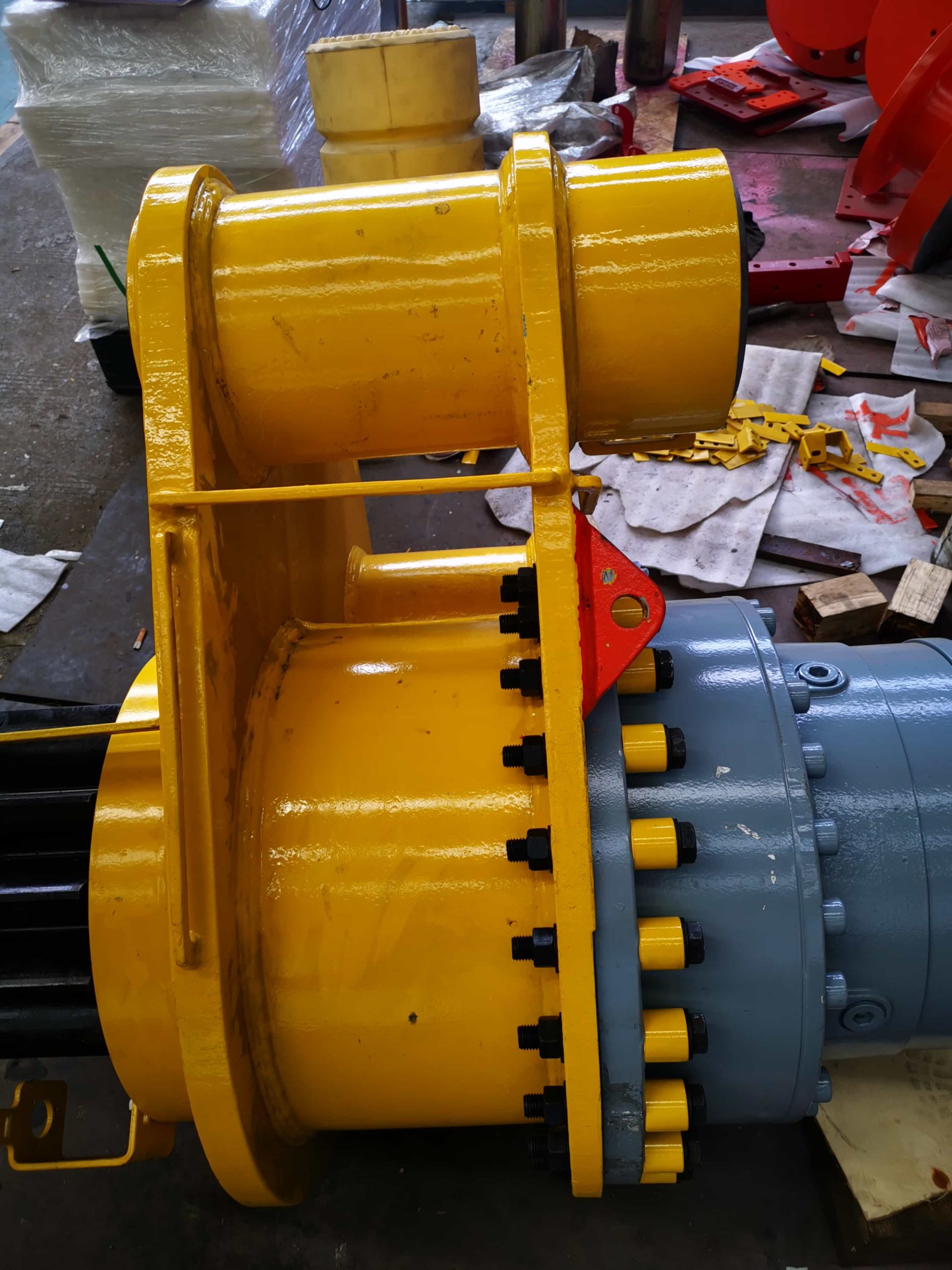
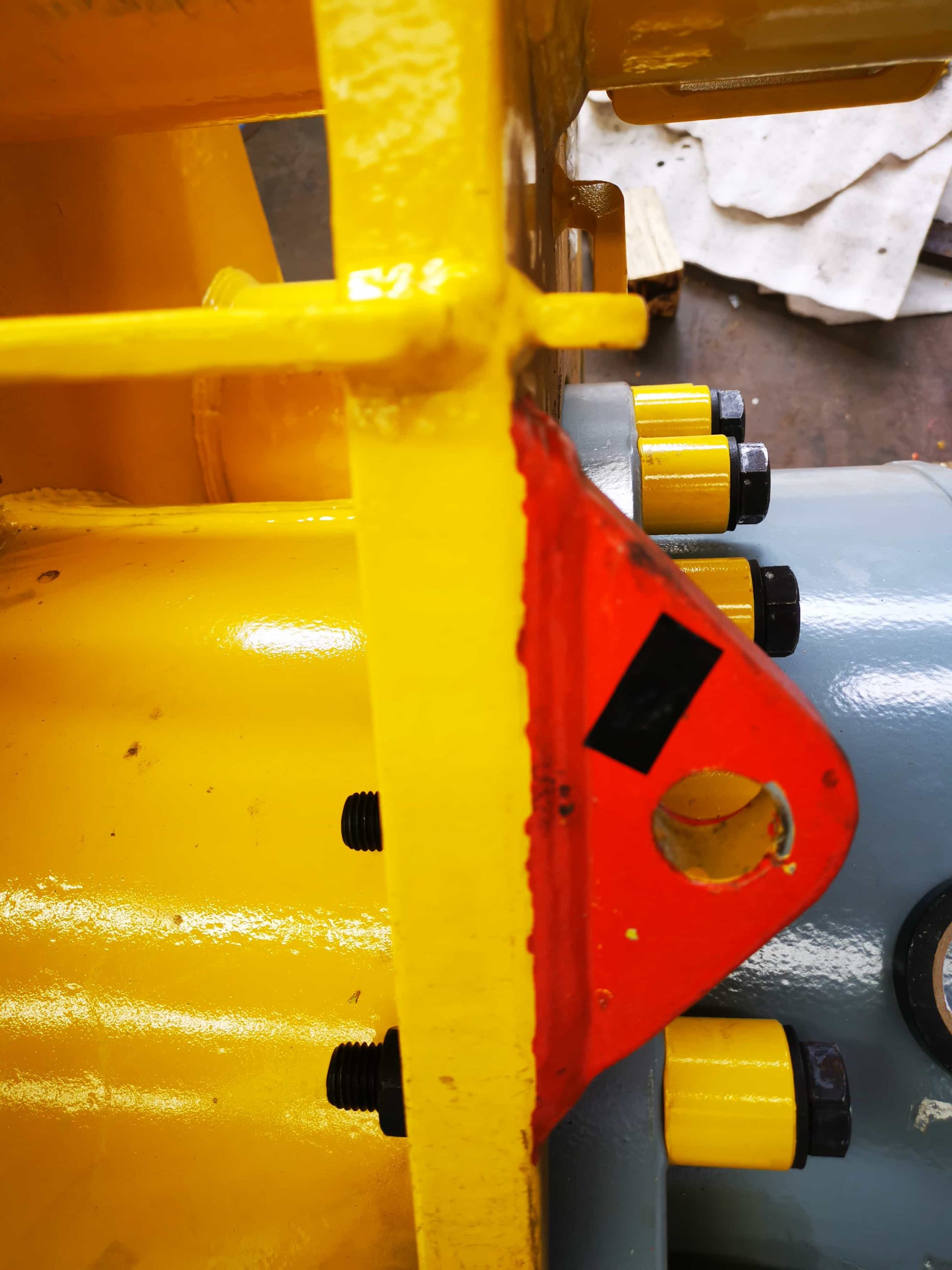
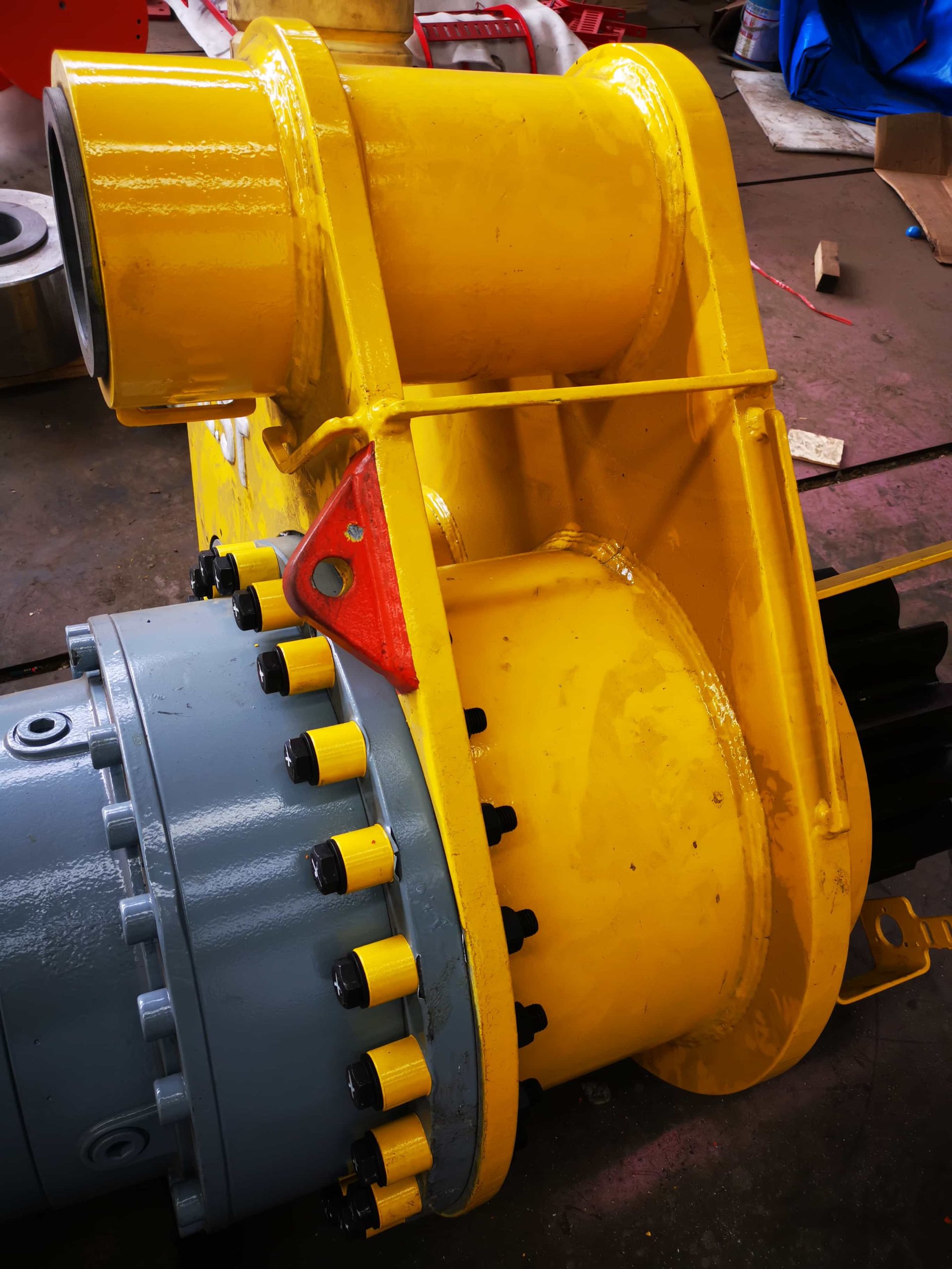
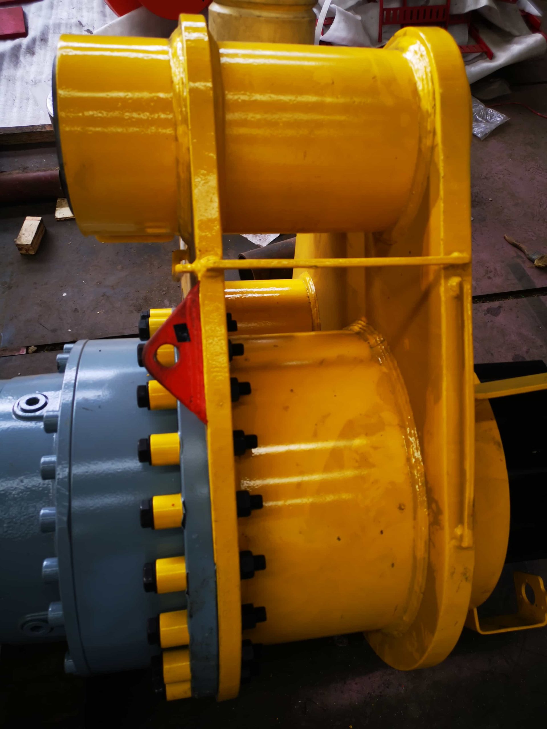
Product Details
A complete hydraulic system consists of five parts, namely power components, actuator components, control components, auxiliary components, and hydraulic medium. The function of power components is to convert the mechanical energy of the prime mover into the pressure energy of the liquid, referring to the oil pump in the hydraulic system, which provides power to the entire hydraulic system. The structural forms of hydraulic pumps generally include gear pumps, vane pumps, and plunger pumps. The function of executing components (such as hydraulic cylinders and hydraulic motors) is to convert the pressure energy of the liquid into mechanical energy, driving the load to perform linear reciprocating or rotary motion. Control components (i.e. various hydraulic valves) control and regulate the pressure, flow rate, and direction of liquids in hydraulic systems. According to the different control functions, hydraulic valves can be divided into pressure control valves, flow control valves, and directional control valves. Pressure control valves are further divided into relief valves (safety valves), pressure reducing valves, sequence valves, pressure relays, etc; The flow control valve includes a throttle valve, an adjustment valve, a diversion and collection valve, etc; Directional control valves include one-way valves, hydraulic control one-way valves, shuttle valves, directional valves, etc. According to different control methods, hydraulic valves can be divided into switch control valves, fixed value control valves, and proportional control valves. Auxiliary components include oil tank, oil filter, oil pipe and pipe joint, sealing ring, pressure gauge, oil level and temperature gauge, etc. Hydraulic oil is the working medium for transmitting energy in hydraulic systems, including various mineral oils, emulsions, and synthetic hydraulic oils.
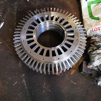
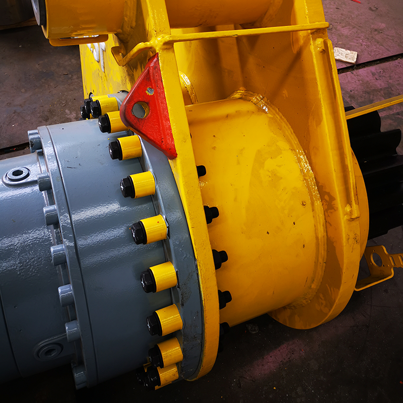
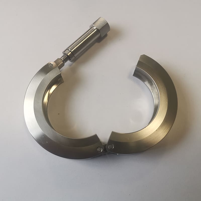
Hydraulic parts, also known as hydraulic components, are the collective name of components used in hydraulic systems, including four categories: power components, actuators, control components and auxiliary components. Gear pumps, vane pumps, hydraulic cylinders, hydraulic motors, hydraulic control valves, oil tanks, pressure gauges and other components are all hydraulic parts. The functions of hydraulic parts vary according to different types. For example, power hydraulic parts convert hydraulic pressure energy, and actuator hydraulic parts convert the hydraulic energy of liquid into mechanical energy.
1. Specific classification:
1. Power components: including gear pumps, vane pumps, plunger pumps, screw pumps, etc.
2. Actuators: mainly hydraulic cylinders and hydraulic motors. Hydraulic cylinders can be divided into piston hydraulic cylinders, plunger hydraulic cylinders, swing hydraulic cylinders, combined hydraulic cylinders, etc. according to different principles; hydraulic motors are gear type, vane type, plunger type, etc.
3. Control components: including directional control valves (check valves, reversing valves), pressure control valves (overflow valves, pressure reducing valves, sequence valves, pressure relays, etc.), flow control valves (throttle valves, speed regulating valves, diverter valves).
4. Auxiliary components: including accumulators, filters, coolers, heaters, oil pipes, pipe joints, oil tanks, pressure gauges, flow meters, sealing devices, pipe fittings, etc.
2. The purpose of each hydraulic component
1. Power element (oil pump) Its function is to convert the mechanical energy of the liquid into hydraulic pressure energy using the prime mover; it is the power part of the hydraulic transmission.
2. Actuator (oil cylinder, hydraulic motor) It converts the hydraulic energy of the liquid into mechanical energy. Among them, the oil cylinder performs linear motion and the motor performs rotational motion.
3. Control elements include pressure valves, flow valves and directional valves. Their function is to steplessly adjust the speed of the hydraulic motor as needed, and to adjust and control the pressure, flow and flow direction of the working fluid in the hydraulic system.
4. Auxiliary components Other components other than the above three parts include pressure gauges, oil filters, accumulators, coolers, pipe fittings (various pipe joints, high-pressure ball valves, quick-change joints, hose assemblies, pressure measuring joints, pipe clamps, etc.) and oil tanks, etc., which are also very important.
5. The working medium refers to the hydraulic oil or emulsion in various types of hydraulic transmission, which realizes energy conversion through the oil pump and the hydraulic motor.
Author: Hydraulic Zhihu
Link: https://zhuanlan.zhihu.com/p/113169473
Source: Zhihu
Copyright belongs to the author. For commercial reprint, please contact the author for authorization, and for non-commercial reprint, please indicate the source.
The hydraulic system composed of hydraulic pump, hydraulic control valve, hydraulic actuator (hydraulic cylinder and hydraulic motor, etc.) and hydraulic auxiliary parts (pipeline and accumulator, etc.) in hydraulic transmission. The hydraulic pump converts mechanical energy into liquid pressure energy, the hydraulic control valve and hydraulic auxiliary parts control the pressure, flow and flow direction of the hydraulic medium, and transmits the pressure energy output by the hydraulic pump to the actuator, which converts the liquid pressure energy into mechanical energy to complete the required action.
Working principle The motor drives the hydraulic pump to suck oil from the oil tank, and the hydraulic pump converts the mechanical energy of the motor into liquid pressure energy. The hydraulic medium enters the left chamber of the hydraulic cylinder through the throttle valve and the reversing valve through the pipeline, pushing the piston to drive the workbench to move right, and the hydraulic medium discharged from the right chamber of the hydraulic cylinder flows back to the oil tank through the reversing valve. After the reversing valve is reversed, the hydraulic medium enters the right chamber of the hydraulic cylinder, causing the piston to move left and pushing the workbench to move in the opposite direction. Changing the opening of the throttle valve can adjust the movement speed of the hydraulic cylinder. The pressure of the hydraulic system can be adjusted by the overflow valve. When drawing a hydraulic system diagram, for the sake of simplicity, the prescribed symbols are used to represent hydraulic components. This symbol is called a functional symbol.
Basic circuit A typical oil circuit composed of relevant hydraulic components to perform specific functions. Any hydraulic transmission system is composed of several basic circuits, and each basic circuit has a certain control function. Several basic circuits are combined together to control the movement direction, working pressure and movement speed of the actuator according to certain requirements. According to different control functions, the basic circuits are divided into pressure control circuits, speed control circuits and direction control circuits.
Pressure control circuit A circuit that uses a pressure control valve (see hydraulic control valve) to control the pressure of the entire system or a local range. According to different functions, pressure control circuits can be divided into four types: pressure regulation, pressure transformation, pressure relief and pressure stabilization. (1) Pressure regulation circuit: This circuit uses a relief valve to adjust the maximum constant pressure of the hydraulic source. The relief valve plays this role. When the pressure is greater than the set pressure of the relief valve, the relief valve opening increases to reduce the output pressure of the hydraulic pump and maintain the system pressure basically constant. (2) Pressure transformation circuit: It is used to change the pressure in a local area of the system. For example, if a pressure reducing valve is connected to the circuit, the pressure after the pressure reducing valve can be reduced; if a booster is connected, the pressure after the booster can be higher than the pressure of the hydraulic source. (3) Pressure relief circuit: When the system does not need pressure or only needs low pressure, the system pressure is reduced to zero pressure or low pressure through the pressure relief circuit. (4) Pressure stabilization circuit: It is used to reduce or absorb the pressure fluctuations generated in the local area of the system and keep the system pressure stable. For example, an accumulator is used in the circuit.
Speed control circuit A circuit that controls the movement speed of the actuator by controlling the flow of the medium. According to different functions, it is divided into speed regulation circuit and synchronization circuit. (1) Speed control circuit: used to control the movement speed of a single actuator. A throttle valve or a speed control valve can be used to control the flow rate. The throttle valve in the schematic diagram of the hydraulic transmission system of a simple grinder plays this role. The throttle valve controls the flow rate of the hydraulic pump into the hydraulic cylinder (the excess flow flows back to the oil tank through the overflow valve), thereby controlling the movement speed of the hydraulic cylinder. This form is called throttling speed control. The speed can also be controlled by changing the output flow rate of the hydraulic pump, which is called volumetric speed control. (2) Synchronous circuit: a circuit that controls the synchronous operation of two or more actuators. For example, the two actuators are rigidly connected to ensure synchronization; the throttle valve or the speed control valve is used to adjust the flow rate of the two actuators to be equal to ensure synchronization; the pipelines of the hydraulic cylinders are connected in series to ensure that the flow rate entering the two hydraulic cylinders is the same, so that the two hydraulic cylinders are synchronized.
Direction control circuit A circuit that controls the flow direction of the hydraulic medium. A circuit that uses a directional control valve to control the movement direction of a single actuator so that it can move in the forward and reverse directions or stop is called a reversing circuit. The reversing valve in the schematic diagram of the hydraulic transmission system of a simple grinder plays this role. A circuit that prevents the actuator from moving due to leakage caused by external factors such as load when the actuator is stopped is called a locking circuit.
Contact Information for Hydraulic Fittings Inquiries
For more information about Hydraulic Fittings or to obtain customized solutions, please contact us:
- Contact Person: Frank
- Tel: 86-510-82305188-8060
- Mobile: 86-18605101203
- Mail: [email protected]
- Address: 15-16F, Building A10, No. 777, JianZhu West Road, Binhu District, Wuxi, Jiangsu, 214072. P.R. China
We look forward to collaborating with you and providing robust support and services for your business.